-
 +994124898416
Contact number
-
 office@marinets.az
Have a question?
-
+994124898416
Contact number
-
office@marinets.az
Have a Question?
Products / Parker / Thermal and Power Management / T-WING Thin Heat Spreaders
T-WING Thin Heat Spreaders
Chomerics’ family of thin heat spreaders provides a low-cost, effective means of cooling IC devices in restricted spaces where conventional heat sinks are inappropriate.
Description
Chomerics’ family of thin heat spreaders provides a low-cost,
effective means of cooling IC devices in restricted spaces where
conventional heat sinks are inappropriate.
T-Wing spreaders consist of 5oz. (0.007inch/0.18mm thick) flexible
copper foil between electrically insulating films. High strength
silicone PSA (pressure-sensitive adhesive) provides a strong bond to
the component. The compliant
nature of these “thermal wing” heat
spreaders permits nearly 100% adhesive contact with non-flat package
surfaces, optimizing thermal and mechanical performance.
Features/Benefits
• Component junction temperature reduction of 10-20°C is common
• Easily added to existing designs to lower component temperatures
and improve reliability
• Custom shapes available for complex designs
Typical Applications
• Microprocessors
• Memory modules
• Laptop PCs and other high density, handheld portable electronics
• High speed disk drives
Design Details
• Low profile (0.33mm/0.013in) allows use in limited space
environments
• Easy peel and stick adhesion to all surfaces, including packages
with residual silicone mold release
• Offers low cost cooling for many package types
• Low application force
(<5psi/ 0.03MPa) minimizes risk of damage to component
• Available in a range of standard sizes
• Pliable nature allows conformance to concave or otherwise non-flat
surfaces for optimal thermal and mechanical performance
• Light weight (0.039 oz/inch2)
• Standard parts are scored for easy forming and alignment
• Easy removal for device replacement
• Available die-cut on continuous rolls
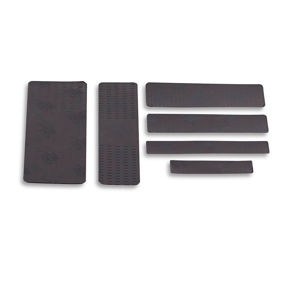
T-Wing® Heat Spreaders
Testing Summary
Summaries of test procedures used for T-Wing heat spreaders are
described below. Thermal performance, adhesion strength and visual
inspection were used as pass/fail criteria.
Apparatus
Anatek® Thermal Analyzer: The ATA was used to measure Rj-a before
and after environmental stressing. PQFP: 196 lead, plastic PQFPs
known to contain silicone mold release were evaluated. T-Wing Heat
Spreader: 1 inch x 4 inch TWing parts were applied to the PQFP
packages with a 5 psi (0.03 MPa) mounting pressure.
Thermal Performance
Various sizes of T-Wing heat spreaders were applied to a 196 lead
PQFP
using less than 5 psi (0.03 MPa) bonding pressure. Within 30 minutes
of application, the test boards were mounted in an Analysis Tech®
thermal analyzer. The devices were heated to equilibrium (45 to 60
minutes) with
approximately 3 watt load on 3 x 3 inch
(7.6 x 7.6 cm) test boards. Two test environments were used:
restricted convention, achieved with a 1 x 5 x 6
inch (2.5 x 12.7 x 15.2 cm) plexiglass
box; and 100 LFM (30m/min) air flow. Results were obtained using
thermocouples for Tc (centered on case) and Rj-a.
Environmental Stressing
Control: Specimens were maintained for 1000 hours at standard
laboratory conditions, 23°C, 35-60% RH.
Heat Aging: Test specimens were placed in a forced convection hot
air oven maintained at 150°C ±5°C for 1000 hours. Test specimens
were then removed and tested.
ElevatedTemperature/HighHumidity: Specimens were placed in a
humidity chamber maintained at 85°C ±2°C and 90%-0 +10% RH for 1000
hours.
Temperature Cycling: Specimens were subjected to 500 cycles from
-50°C
to +150°C in a Tenney Temperature Cycling Oven.
Temperature Shock: Specimens were subjected to 100 temperature
shocks by immersion into -50° and +150°C liquids. Temperatures were
monitored with thermocouples.
Evaluation Procedure
Visual: All test specimens were exam- ined for de-bonding,
delamination or other signs that the tape was failing after
environmental stress.
Thermal Performance: T-Wing was applied to the PQFP with 5 psi
mount- ing pressure. After a one hour dwell, the Rj-a of each
specimen was mea- sured at 100 LFM and under restricted convection
conditions. The Rj-a was again measured after environmental
stressing.
90° Peel Strength: A T-Wing heat spreader was applied to each PQFP
with 5 psi mounting pressure. The specimens were subjected to
environ- mental stress and then tested for 90° peel strength at room
temperature.

